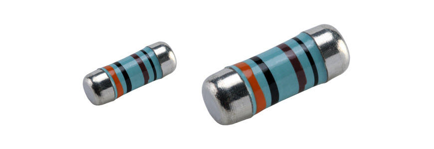


Resistor
Thin film Precision resistor 0.01%, TC2ppm, wirebondale, Anti-Crossive, MELF. Current sensing, Metal...
View More
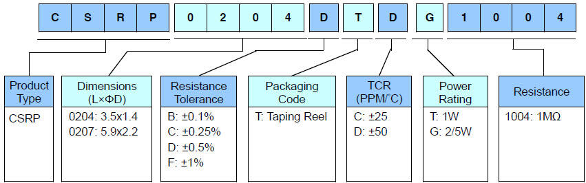
Part Number:CSRP0204FTDG1004
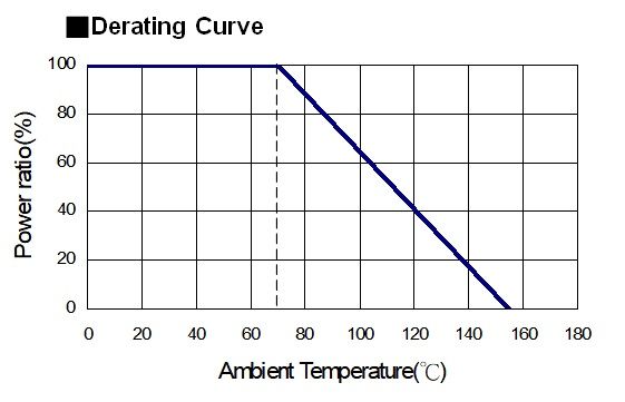
| Item Type | Power Rating at 70°C |
Operating Temp. Range | Max. Operating Voltage | Max. Overload Voltage | Resistance Range | TCR (PPM/°C) |
|||
|---|---|---|---|---|---|---|---|---|---|
| ±0.1% | ±0.25% | ±0.5% | ±1% | ||||||
| 0204 | 2/5W | -55 ~ +155°C | 500V | 1000V | 340KΩ-1MΩ | 340KΩ-3.4MΩ | ±25 | ||
| 340KΩ-1MΩ | 340KΩ-3.4MΩ | ±50 | |||||||
| 0207 | 1W | -55 ~ +155°C |
1000V | 2000V | 340KΩ-1MΩ | 340KΩ-3.4MΩ | ±25 | ||
| 340KΩ-1MΩ | 340KΩ-3.4MΩ | ±50 | |||||||
Operating Voltage=√(P*R) or Max. operating voltage listed above, whichever is lower.
Overload Voltage=2.5*√(P*R) or Max. overload voltage listed above, whichever is lower.
RCWV(Rated Continuous Working Voltage)=√(P*R) or Max. Operating Voltage whichever is lower.
☑ Helisto is capable of manufacturing the optional spec based on customer's requirement.
The single impulse graph is the result of 50 impulses of rectangular shape applied at one-minute intervals. The limit of acceptance was a shift in resistance of less than 1% from the initial value. The power applied was subject to the restrictions of the maximum permissible impulse voltage graph shown.
The continuous load graph was obtained by applying repetitive rectangular pulses where the pulse period was adjusted so that the average power dissipated in the resistor was equal to its rated power at 70°C. Again the limit of acceptance was a shift in resistance of less than 1% from the initial value.
Resistors are tested in accordance with IEC 60115-1 using both 1.2/50us and 10/700us pulse shapes. The limit of acceptance is a shift in resistance of less than 0.5% from the initial value.

Thin film Precision resistor 0.01%, TC2ppm, wirebondale, Anti-Crossive, MELF. Current sensing, Metal...
View More
Ceramic high frequency chip inductors, small size to 01005. Thin film, multilayer, wirewound , ferrite...
View More
Multilayer Ceramic capacitor offers high Voltage, high frequency, low noise, High Q, Low TCR. NPO, X7R,...
View More